
Introduction
In the premium automotive aftermarket, a custom forged wheel is ultimately defined by two distinct phases of its creation. The first phase—the forging process—utilizes immense heat and millions of pounds of hydraulic pressure to forge a solid block of aerospace-grade aluminum into an unbreakable, dense canvas. It is this process that dictates the wheel’s ultimate strength.
However, it is the second phase that dictates the wheel’s soul, fitment, and dynamic performance: CNC Machining.
Computer Numerical Control (CNC) machining is where raw metallurgy meets micrometer-level precision. It is the highly automated, meticulously programmed process of stripping away excess metal to reveal a lightweight, aerodynamically optimized, and visually stunning automotive masterpiece. Without advanced CNC technology, the intricate spoke designs, aggressive concavity, and exact bespoke fitments demanded by today’s supercars and luxury vehicles would be physically impossible to produce.
At CN Wheel Rims (CNWR), our manufacturing facility is equipped with a state-of-the-art battery of multi-axis CNC lathes and milling centers. As a globally trusted OEM wheel supplier, we leverage this technology to turn structural blanks into precision-engineered custom forged wheels.
In this comprehensive guide, we will take you inside the CNC machining phase of the wheel manufacturing process. We will explore the engineering software behind the cuts, the difference between lathe turning and multi-axis milling, and why CNC precision is the ultimate differentiator for B2B distributors and performance enthusiasts.
The Pre-Machining Phase: Where Engineering Meets Design
Before a cutting tool ever touches the 6061-T6 aluminum blank, hours of rigorous digital engineering must take place. CNC machines are only as intelligent as the code that drives them.
1. CAD (Computer-Aided Design)
The journey begins in the digital realm. Our engineers use advanced CAD software to draft the exact 3D model of the custom forged wheel. For B2B clients utilizing our OEM/ODM services, this is where we translate a brand’s conceptual sketch into a mathematically perfect 3D geometry. Every curve, chamfer, and lug hole is plotted with exact coordinates.
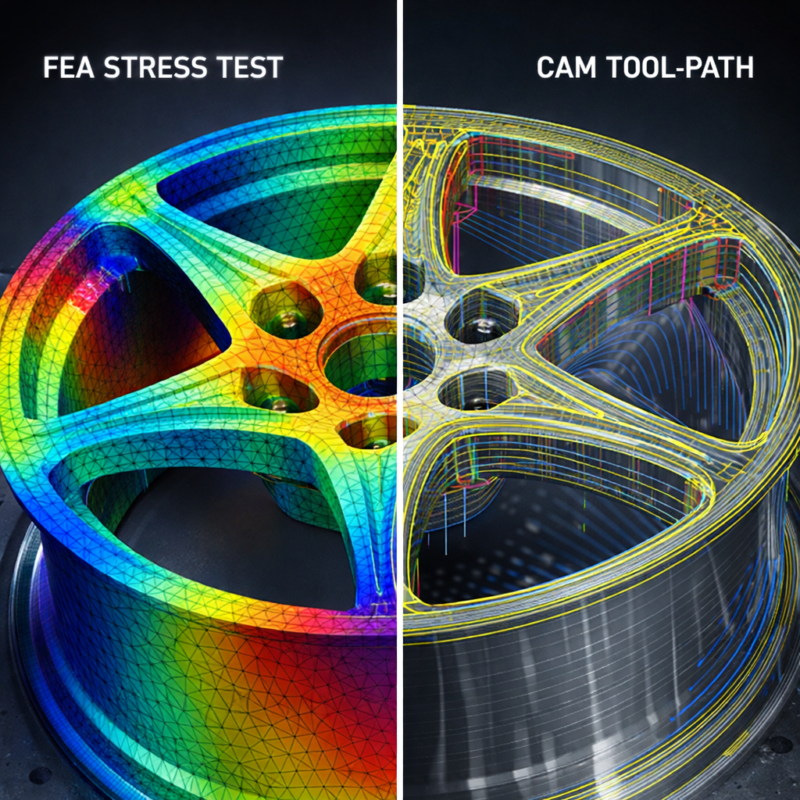
2. FEA (Finite Element Analysis)
Once the CAD model is designed, it must be virtually stress-tested. FEA software simulates the real-world physical forces the wheel will endure—including cornering loads, radial fatigue, and sudden impacts.
-
If the FEA software detects a “hot spot” where stress concentration is too high, the engineer thickens the spoke in the CAD model.
-
Conversely, if an area is over-engineered and carrying dead weight, the engineer adds “weight-reduction pockets” to the design.
3. CAM (Computer-Aided Manufacturing)
After the design passes FEA safety testing, the CAD file is exported into CAM software. CAM translates the 3D model into “G-code”—the exact numeric language the CNC machine understands. The CAM programmer dictates the tool paths, spindle speeds, feed rates, and the specific carbide cutting tools required for every single pass.
The CNC Machining Process: Step-by-Step
Transforming a solid, heavy forged blank into a feather-light custom forged wheel requires passing through different specialized CNC machines.
Step 1: CNC Lathe Turning (Shaping the Profile)
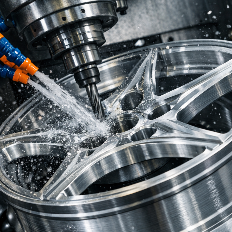
The forged 6061-T6 blank—which at this stage looks like a heavy, solid metal drum—is loaded into a heavy-duty CNC lathe. Unlike a mill, which moves a spinning cutter over a stationary part, a lathe spins the wheel blank at high speeds while a stationary cutting tool presses against it. The lathe systematically cuts the inner and outer barrel profiles, establishes the exact width of the wheel, and trims the outer lip to the precise diameter. This process ensures the wheel is perfectly round, establishing a flawless baseline concentricity.
Step 2: Multi-Axis CNC Milling (Carving the Face)
Once the barrel and profile are turned on the lathe, the blank is transferred to a CNC milling center. This is where the aesthetic design is born. Using a carousel of different diamond-tipped and carbide end-mills, the machine systematically plunges into the aluminum, carving out the negative space between the spokes. It operates with micrometer precision, executing the G-code to mill the complex face design, cut the intricate chamfers, and engrave any custom branding or logos into the center cap area or lip.
Step 3: Drilling the PCD and Center Bore
Fitment is everything in custom wheels. During the milling phase, the machine drills the exact Pitch Circle Diameter (PCD)—also known as the bolt pattern (e.g., 5×112, 5×114.3). Simultaneously, the center bore is milled to the exact fractional millimeter of the target vehicle’s hub. This guarantees a true “hub-centric” fitment, eliminating the need for aftermarket plastic centering rings and ensuring zero vibration at high speeds.
Step 4: Weight Reduction Pocketing
A hallmark of premium CNC machining in forged wheel manufacturing is back-pad pocketing. The CNC mill flips the wheel and cuts strategic cavities into the back of the mounting pad and the sides of the spokes. This extracts unnecessary metal from the areas that do not bear structural loads, further reducing the wheel’s rotational mass.
3-Axis vs. 5-Axis CNC Machining: The Technological Divide
Not all CNC machines are created equal. The complexity of the wheel design dictates the type of machine required, and this is a major factor separating budget manufacturers from elite OEM wheel suppliers like CNWR.
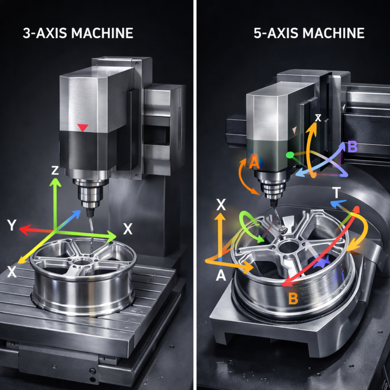
3-Axis CNC Machining
A 3-axis mill operates along the X (left-to-right), Y (front-to-back), and Z (up-and-down) axes.
-
Capabilities: It is excellent for flat, simple, or highly geometric spoke designs.
-
Limitations: Because the cutting tool only points straight down, it cannot easily cut deep undercuts or complex curving profiles on the sides of spokes without the operator manually stopping the machine, unbolting the wheel, and rotating it to a new angle. This multiple-setup process increases manufacturing time and introduces a slight risk of alignment error.
5-Axis CNC Machining
A 5-axis mill includes the standard X, Y, and Z axes, but adds two rotational axes (A and B). This allows either the cutting tool to pivot, or the table holding the wheel to tilt and rotate in space.
-
Capabilities: 5-axis machining is the pinnacle of wheel manufacturing technology. It allows the cutting tool to approach the 6061-T6 aluminum from virtually any angle.
-
The Result: This technology enables the creation of sweeping, organic spoke designs, aggressive deep-concave profiles, and complex floating spokes. Because the machine can reach every surface without unbolting the wheel, it executes the entire program in a single setup. This guarantees absolute structural symmetry, faster production times, and zero human alignment errors.
Why CNC Precision Matters for Performance and Safety
When you bolt a set of custom forged wheels onto a high-performance vehicle, the precision of the CNC machining dictates how the car will behave at 150 mph.
1. Eliminating Runout and Vibrations
Runout is the measure of a wheel’s imperfection from a perfect circle. If a wheel is poorly machined, it will wobble slightly as it rotates, causing severe steering wheel vibrations and premature tire wear. Because CNWR utilizes rigid, highly calibrated CNC machines that carve the wheel in singular, continuous setups, our forged wheels boast industry-leading low runout tolerances. They spin glassy-smooth, even at extreme track speeds.
2. Perfect Brake Clearance for BBK
High-performance cars utilize massive Big Brake Kits (BBK) with large, multi-piston calipers. Off-the-shelf cast wheels often struggle to clear these brakes, forcing owners to use dangerous wheel spacers. Precision CNC machining allows our engineers to calculate the exact sweep profile of a specific vehicle’s brake caliper and program the CNC mill to cut the backside of the spokes just millimeters away from the brake, ensuring a flush, safe, spacer-free fitment.
3. Optimizing Rotational Inertia
Every ounce of metal removed by the CNC machine during the pocketing phase reduces the wheel’s unsprung mass. However, where that metal is removed matters. CNC precision allows us to aggressively mill the outer circumference of the wheel. Reducing weight furthest from the hub drastically lowers the rotational inertia, allowing the vehicle to accelerate faster and brake shorter.
Partnering with a High-Tech Manufacturer
For B2B buyers, wholesale distributors, and independent aftermarket brands, your reputation hinges on the quality of the products you supply. Partnering with an OEM wheel supplier equipped with top-tier CNC capabilities offers massive commercial advantages.
-
Infinite Customization for Your Clients: With multi-axis CNC milling, you can confidently tell your retail clients, “Yes, we can build that.” Whether they need an obscure PCD for a classic restoration, a unique offset for a widebody kit, or a completely bespoke spoke design, CNC technology makes rapid prototyping and production highly scalable.
-
White-Label OEM/ODM Services: At CNWR, our engineering and machining departments serve as your in-house factory. You can bring us a napkin sketch or a CAD concept, and we will handle the FEA testing, CNC programming, and physical milling to produce an exclusive line of custom forged wheels under your brand name.
-
Reliable Lead Times: Advanced CAM programming and 5-axis machining drastically reduce the time a wheel spends on the factory floor. Single-setup machining means higher throughput, allowing CNWR to deliver your wholesale inventory and custom orders efficiently and predictably.
Frequently Asked Questions (FAQs)
How long does it take to CNC machine a forged wheel? The machining time varies heavily depending on the complexity of the design. A simple monoblock wheel might spend 2 to 4 hours in the CNC mill. A highly intricate, 3-piece VIP style face with complex undercuts and deep pocketing might require 6 to 10 hours of continuous 5-axis machining.
Can CNC machining weaken a forged wheel? If done incorrectly, yes. If too much material is milled away from load-bearing areas (like the spoke roots or the hub), the wheel can fail. This is exactly why rigorous FEA (Finite Element Analysis) is mandatory before the CAM code is written. CNWR’s engineering process ensures that metal is only removed from structurally safe zones.
What happens to all the aluminum shavings cut away by the CNC machine? Because forged wheels begin as solid billets, a significant percentage of the material is milled away. These aluminum chips are meticulously collected, cleaned of cutting fluids, and recycled back into the global aluminum supply chain, making the CNC process highly sustainable.
Can CNC machines cut any design into a wheel? With 5-axis technology, almost any structural design is possible. However, the design must still pass FEA safety testing. Our engineers occasionally have to slightly modify a client’s aesthetic concept to ensure the spokes are thick enough to support the target vehicle’s gross weight. Safety and structural integrity always dictate the final CNC tool path.
Conclusion
The transformation of a raw, 6061-T6 aluminum forging into a bespoke automotive masterpiece is a triumph of modern engineering. CNC machining represents the ultimate marriage of digital design and physical execution. It is the process that dictates perfect fitment, guarantees vibration-free performance, and allows for the breathtaking, ultra-lightweight designs that define the premium wheel industry.
Whether you are a performance driver demanding exact brake clearances and minimized unsprung mass, or a B2B distributor looking to launch an exclusive line of OEM products, the capabilities of your manufacturer’s CNC department will make or break your success.
At CN Wheel Rims (CNWR), our investment in world-class, multi-axis CNC technology allows us to deliver uncompromising precision from block to rim.